In the field of MEMS systems, capacitive accelerometers have become a cornerstone technology for inclination or tilt sensing. These devices, essential for various industrial and consumer applications, face significant challenges, especially in dynamic environments where vibration and shock are prevalent. Achieving high precision, such as 0.1° tilt accuracy, requires addressing a range of technical specifications and error factors. This article delves into the key criteria and solutions for effective tilt sensing using MEMS accelerometers.
1.Key Criteria for Accurate Tilt Sensing
Bias Stability: Bias stability refers to the accelerometer's ability to maintain a consistent zero-g offset over time. High bias stability ensures that the sensor readings remain reliable and do not drift, which is crucial for maintaining accuracy in tilt measurements.
Offset Over Temperature: Temperature variations can cause shifts in the accelerometer's zero-g offset. Minimizing these shifts, known as tempco offset, is essential to maintain accuracy across different operating conditions.
Low Noise: Noise in sensor readings can significantly affect the accuracy of tilt measurements. Low-noise accelerometers are vital for achieving precise and stable tilt readings, particularly in static environments.
Repeatability: Repeatability refers to the sensor's ability to produce the same output under identical conditions over multiple trials. High repeatability ensures consistent performance, which is critical for reliable tilt sensing.
Vibration Rectification: In dynamic environments, vibration can distort tilt data. Effective vibration rectification minimizes the impact of these disturbances, allowing for accurate tilt measurements even when the sensor is subjected to external vibrations.
Cross-Axis Sensitivity: This parameter measures how much the sensor output is affected by accelerations perpendicular to the measurement axis. Low cross-axis sensitivity is essential to ensure that the accelerometer responds accurately to tilt along the intended axis only.
2.Challenges in Dynamic Environments
Dynamic environments pose significant challenges for MEMS accelerometers in tilt sensing applications. Vibration and shock can introduce errors that corrupt tilt data, leading to significant measurement inaccuracies. For instance, achieving <1° tilt accuracy is extremely challenging in such conditions, while attaining >1° accuracy is more feasible. Understanding the sensor's performance and the application's environmental conditions is crucial to optimizing tilt measurement accuracy.
3.Error Sources and Mitigation Strategies
Several error sources can affect the accuracy of MEMS accelerometers in tilt sensing:
Zero-g Bias Accuracy and Shift: Zero-g bias errors can arise from soldering, PCB enclosure alignment, and temperature changes. Postassembly calibration can reduce these errors.
Sensitivity Accuracy and Tempco: Variations in sensitivity due to temperature changes must be minimized to ensure accurate readings.
Nonlinearity: Nonlinear responses can distort measurements and need to be corrected through calibration.
Hysteresis and Long-Term Stability: Hysteresis and stability over the sensor's lifetime can impact accuracy. These issues are often addressed through high-quality manufacturing and design practices.
Humidity and PCB Bending: Environmental factors such as humidity and mechanical stresses from PCB bending can introduce additional errors. In-situ servicing and environmental controls are necessary to mitigate these effects.
Bridge Monitoring Using Mems Accelerometers
For example, the ER-MA-5 High Accuracy MEMS Accelerometer is tailored specifically for inclination applications. It boasts the bias stability of 5 μg and resolution of 5 μg The factory calibration characterizes the entire sensor signal chain for sensitivity and bias over a specified temperature range (typically −40°C to +80°C), ensuring high precision and reliability upon installation. It is suitable for long-term installation in hydraulic structures such as concrete dams, panel dams, and earth-rock dams, as well as in civil and industrial buildings, roads, bridges, tunnels, roadbeds, and civil engineering foundations. It facilitates the measurement of inclination changes and enables the automated collection of measurement data.
Conclusion
MEMS capacitive accelerometers are pivotal in achieving accurate tilt sensing, but they must overcome various challenges, especially in dynamic environments. Key criteria such as bias stability, offset over temperature, low noise, repeatability, vibration rectification, and cross-axis sensitivity play critical roles in ensuring precise measurements. Addressing error sources through calibration and employing integrated solutions like iSensors can significantly enhance the performance and reliability of tilt sensing systems. As technology advances, these sensors will continue to evolve, offering even greater accuracy and robustness for a wide range of applications.
The differences between a triaxial quartz flexible accelerometer and a uniaxial quartz flexible accelerometer primarily revolve around the number of axes they can measure, their application scope, and the complexity of the data they provide.
Single-axis quartz accelerometers are commonly found in the market. These devices measure acceleration in only one direction (X, Y, or Z axis) and are ideal for applications needing specific directional acceleration monitoring. In contrast, triaxial quartz accelerometers are essential for multidimensional motion analysis in fields like aerospace, marine, automotive, earthquake monitoring, and complex mechanical systems. They provide comprehensive data for precision navigation, attitude control, motion capture, and 3D spatial analysis.
The ER-3QA-02D High Precision Three Axis Quartz Accelerometer is a high-precision device consisting of three A15 acceleration sensors, a 24-bit high precision A/D converter, a 16-bit ultra-low power microcontroller, and a mechanical structure. It features digital output, high precision, temperature compensation, and low power consumption, making it suitable for a wide range of advanced applications.
For more information, contact ERICCO INERTIAL SYSTEM:
WhatsApp/WeChat/Mobile: +8613992884879
Website:
Three Axis Quartz Accelerometer Supplier - ERICCO China
Ericco is China specialized Three Axis Quartz Accelerometer supplier, provides low cost Quartz Accelerometer to the customers worldwide.
The ER-QA-01A3 model is designed for applications that demand the highest levels of accuracy and performance. Here are the key features that set it apart:
High Precision: With a bias of ≤1 mg, the ER-QA-01A3 offers unparalleled precision compared to other models in the ER-QA-01A series, making it suitable for the most exacting measurement tasks.
Superior Temperature Stability: The bias temperature coefficient is ≤10 μg/℃, ensuring consistent performance across a wide range of temperatures. This makes the ER-QA-01A3 highly reliable in dynamic and fluctuating environments.
Enhanced Repeatability: The ER-QA-01A3 boasts bias repeatability of ≤10 μg and scale factor repeatability of ≤10 ppm, ensuring that measurements remain consistent over time, which is crucial for long-term applications.
Minimal Non-linearity: With a second-order non-linearity of ≤10 μg/g², the ER-QA-01A3 maintains high accuracy in its readings, further cementing its suitability for precision-demanding applications.
Robust Performance: The ER-QA-01A3 operates effectively within a temperature range of -40 to +80℃, can endure vibrations up to 8 grms, and withstands shocks of 120g for 4.5 ms. These features ensure that it performs reliably under harsh conditions.
Choosing the ER-QA-01A3 means opting for accuracy, reliability, and superior performance. Whether in aerospace, navigation, or other fields requiring precise inertial measurements, the ER-QA-01A3 delivers outstanding results.
For more information about the ER-QA-01A3 and other high-precision instruments, visit Ericco Inertial System or contact their support team.
WhatsApp/WeChat/Mobile: +8613992884879
Website:
Invest in precision. Choose the ER-QA-01A3 Quartz Accelerometer for your high-accuracy needs.
What is the Most Accurate Quartz Accelerometer Provided by Ericco Inertial System?
Introducing the ER-QA-01A3 Quartz Accelerometer
The ER-QA-01A3 model is designed for applications that demand the highest levels of accuracy and performance. Here are the key features that set it apart:
1.High Precision: With a bias of ≤1 mg, the ER-QA-01A3 offers unparalleled precision compared to other models in the ER-QA-01A series, making it suitable for the most exacting measurement tasks.
2. Superior Temperature Stability: The bias temperature coefficient is ≤10 μg/℃, ensuring consistent performance across a wide range of temperatures. This makes the ER-QA-01A3 highly reliable in dynamic and fluctuating environments.
3. Enhanced Repeatability: The ER-QA-01A3 boasts bias repeatability of ≤10 μg and scale factor repeatability of ≤10 ppm, ensuring that measurements remain consistent over time, which is crucial for long-term applications.
4. Minimal Non-linearity: With a second-order non-linearity of ≤10 μg/g², the ER-QA-01A3 maintains high accuracy in its readings, further cementing its suitability for precision-demanding applications.
5. Robust Performance: The ER-QA-01A3 operates effectively within a temperature range of -40 to +80℃, can endure vibrations up to 8 grms, and withstands shocks of 120g for 4.5 ms. These features ensure that it performs reliably under harsh conditions.
6. Versatile Application: Ideal for use in microgravity measuring systems, inertial navigation systems, vibration analysis, and static angle measurement systems, the ER-QA-01A3 is versatile and adaptable to various high-precision applications.
Why Choose the ER-QA-01A3?
Choosing the ER-QA-01A3 means opting for accuracy, reliability, and superior performance. Whether in aerospace, navigation, or other fields requiring precise inertial measurements, the ER-QA-01A3 delivers outstanding results.
For more information about the ER-QA-01A3 and other high-precision instruments, visit Ericco Inertial System or contact their support team.
WhatsApp/WeChat/Mobile: +8613992884879
Website:
Designed for the rigorous demands of the oil and gas industry, the ER-QA-03D Quartz Accelerometer offers unparalleled performance and reliability. This state-of-the-art accelerometer excels in both static and dynamic measurements, making it an essential tool for:
· Measurement-While-Drilling (MWD)
· Logging-While-Drilling (LWD)
· Inertial Navigation
· Oil Well Logging
· Gyro Inclinometers
· Guidance and Control Systems
Key Features:
· Exceptional Durability: Withstands extreme shocks and temperatures, ensuring accurate performance in harsh conditions.
· High Precision: Incorporates advanced temperature compensation to minimize error, providing consistent and reliable data.
· Versatile Applications: Ideal for use in aerospace, industrial measurements, and oil and gas exploration.
Why Choose ER-QA-03D?
· Robust Construction: Designed to operate reliably under extreme conditions.
· High Accuracy: Delivers precise measurements crucial for critical applications.
· Reliable Performance: Consistent results, even in challenging environments.
Upgrade your measurement capabilities with the ER-QA-03D Anti-Shock and High-Temp Quartz Accelerometer, the reliable choice for professionals in demanding fields.
For more information, contact ERICCO INERTIAL SYSTEM:
The application of GNSS technology is both the fundamental purpose and the ultimate goal of the navigation satellite system. The satellite navigation market can generally be divided into three segments: the professional market, the mass market, and the security market. From an application perspective, the global satellite navigation system can be categorized into the following 10 areas:
Agriculture:
Precision Farming: GNSS allows for precise mapping of fields, guiding tractors and machinery to plant seeds, apply fertilizers, and harvest crops with pinpoint accuracy. This reduces wastage and ensures uniform application, leading to better crop yields and lower costs.
Yield Mapping: Farmers use GNSS to create yield maps that show how much crop was harvested in different parts of a field, helping to identify areas that need more attention.
The integration of GNSS in agriculture is revolutionizing traditional farming practices, leading to significant efficiency gains and sustainability. However, it risks widening the gap between large agribusinesses and small farmers who cannot afford this advanced technology, potentially exacerbating economic inequalities in rural areas.
Fig.1 Precision Agriculture
Construction:
Site Surveying: GNSS technology provides accurate measurements for site surveying, which is crucial for the planning and execution of construction projects. This ensures that structures are built according to precise specifications.
Machine Control: Heavy machinery equipped with GNSS can perform tasks like excavation, grading, and paving with high precision, reducing the need for manual supervision.
GNSS is indispensable in modern construction, enabling projects to be completed faster and with greater accuracy. However, the industry's heavy dependence on it highlights a need for backup systems to mitigate potential satellite signal losses, ensuring continuous operation.
Telecommunications:
Network Synchronization: GNSS provides precise timing signals necessary for synchronizing telecommunications networks. This ensures seamless data transmission, essential for mobile phone networks and the internet.
Infrastructure Monitoring: GNSS technology is used to monitor and manage the physical infrastructure of telecom networks, ensuring optimal performance.
Telecommunications infrastructure's dependence on GNSS for synchronization is a critical vulnerability. Disruptions in GNSS signals can lead to network outages, affecting millions of users and potentially causing widespread disruption in communication services.
Transportation and Logistics:
Fleet Management: GNSS enables real-time tracking of vehicles, allowing companies to monitor their fleets, optimize routes, and reduce fuel consumption. This leads to cost savings and improved delivery times.
Supply Chain Management: GNSS improves the visibility and coordination of goods movement, reducing delays and ensuring timely delivery.
While GNSS improves efficiency in logistics and enhances customer satisfaction, there is an over-reliance on this technology. Any disruptions in satellite services, whether due to technical failures or malicious attacks, could lead to significant operational challenges and financial losses.
Fig.2 Overview Of Cloud Based Gnss Positioning Architecture
Aviation:
Navigation and Landing: GNSS technology supports aircraft navigation, ensuring that planes follow precise routes. It also aids in landing, especially in poor visibility conditions, enhancing safety.
Air Traffic Management: GNSS contributes to more efficient air traffic management, reducing delays and increasing the capacity of airspace.
GNSS has transformed aviation by significantly improving navigation and safety. However, its susceptibility to jamming and spoofing remains a significant security concern. The aviation industry must invest in robust countermeasures to protect against these threats.
Marine and Fisheries:
Navigation and Monitoring: GNSS aids in marine navigation, helping ships to chart their courses accurately. It also monitors fishing activities, ensuring compliance with regulations and sustainable practices.
Environmental Protection: GNSS is used to monitor ocean conditions, track pollution, and protect marine ecosystems.
The widespread use of GNSS in marine industries enhances safety and sustainability. However, it also raises issues of maritime sovereignty and privacy, as vessels can be tracked and monitored by various entities, potentially leading to geopolitical tensions.
Emergency Services:
Disaster Response: GNSS is crucial in disaster response, helping emergency teams to locate affected areas, coordinate rescue operations, and deliver aid efficiently.
Public Safety: GNSS is used by police, fire services, and ambulances for rapid response and effective coordination during emergencies.
Reliance on GNSS in emergency services is a double-edged sword; it enhances response times and saves lives, but can be crippled by natural or human-made disruptions. Building resilient systems that can operate independently of GNSS technology during crises is essential.
Urban Planning and Management:
Smart Cities: GNSS data is used in urban planning to optimize traffic flow, manage public transportation, and improve resource management. This contributes to the development of smart city infrastructure.
Infrastructure Monitoring: GNSS helps monitor the health of infrastructure, such as bridges and roads, ensuring timely maintenance and safety.
Smart cities powered by GNSS are the future, offering enhanced efficiency and quality of life. However, they also raise significant concerns about data privacy and surveillance, as the vast amount of data collected can be misused if not properly regulated and protected.
Environmental Monitoring:
Climate and Ecosystem Tracking: GNSS helps track climate change by monitoring sea level rise, glacier movements, and changes in vegetation. It also supports ecosystem conservation by tracking wildlife and mapping habitats.
Disaster Prediction and Management: GNSS is used in predicting natural disasters such as earthquakes and tsunamis, providing early warnings and aiding in disaster management.
GNSS is invaluable for environmental monitoring, providing critical data for understanding and mitigating climate change. Yet, its environmental footprint, including the space debris from satellite launches and the energy consumption of ground-based systems, is often overlooked and needs to be addressed to ensure sustainability.
Military and Defense:
Strategic Operations: GNSS is essential for military navigation, targeting, and strategic operations, providing accurate positioning and timing information crucial for mission success.
Surveillance and Reconnaissance: GNSS aids in surveillance and reconnaissance operations, enhancing situational awareness and intelligence gathering.
The military's dependence on GNSS for critical operations is both a strength and a vulnerability. While it enhances operational effectiveness, it also presents a significant target for adversaries. Developing resilient and secure systems that can operate independently of GNSS technology is crucial for maintaining national security.
In conclusion, GNSS technology plays a pivotal role across various industries, driving innovation and efficiency. However, its widespread adoption also brings challenges, including over-reliance, security vulnerabilities, and ethical concerns. Addressing these issues is vital as GNSS continues to integrate more deeply into our daily lives and industrial processes.
If you want to get more details about Satellite receiver ,pls visit
With the development of MEMS technology, inertial sensor devices have become one of the most successful and widely used MEMS devices in the past few years, and micro-accelerometers are an outstanding representative of inertial sensor devices. One such technological advancement is the application of Micro-Electro-Mechanical Systems (MEMS) accelerometers in petroleum logging.
1.Understanding MEMS Accelerometers
MEMS accelerometers are tiny devices that measure acceleration forces, which can be static (like gravity) or dynamic (caused by movement or vibrations). They are constructed using microfabrication technology, allowing for the integration of mechanical and electrical components on a single silicon chip. This integration results in highly sensitive, accurate, and robust sensors that can be used in a wide range of applications.
The theoretical basis of the micro-accelerometer is Newton's second law. According to the basic physical principle, within a system, the speed cannot be measured, but its acceleration can be measured. If the initial velocity is known, the linear velocity can be calculated by integrating, and then the linear displacement can be calculated. Combined with a gyroscope (used to measure angular velocity), objects can be precisely positioned. According to this principle, people have long used accelerometers and gyroscopes for navigation of ships, aircraft and spacecraft.
2.MEMS Accelerometers Advance Oil and Gas Drilling Efficiency
In resource exploration, inertial technology is mainly used to measure the trajectory of the well and the actual position of the bit, so as to ensure that the well depth reaches the predetermined position. With the depletion of petroleum resources, exploration and development becomes more and more complicated, so higher precision and more reliable oil inclinometer are needed.
The application of inertial technology can meet this requirement. By using high-precision and high-resolution inertial and magnetic sensors to accurately measure engineering parameters such as inclination Angle, azimuth Angle and tool face Angle during drilling, real-time monitoring of well trajectory and bit position can be realized. Among them, capacitive MEMS accelerometers are relatively mature in terms of high temperature resistance, impact resistance and accuracy.
Among them, capacitive mems accelerometers are relatively mature in high temperature resistance, shock resistance and accuracy. ERICCO's ER-MA-5 High Accuracy MEMS Accelerometer has the characteristics of small volume, light weight and low energy consumption that can be widely used in Inertial measurement: inertial guidance, overload measurement, combined navigation;Tilt measurement: antenna attitude, platform measurement, dip test; Vibration measurement: mechanical equipment, bridge dam, safety test.
Fig.2 High-Accuracy-MEMS-Accelerometer
Two applications in petroleum logging are as follows:
Borehole Seismic Surveys:
Vertical Seismic Profiling (VSP): MEMS accelerometers are used in VSP to provide detailed images of the subsurface geological structures. These sensors measure the seismic waves generated by a source at the surface and reflected back from various geological layers. The data collected helps in identifying oil and gas reservoirs, mapping the subsurface, and planning drilling operations.
Seismic While Drilling (SWD): This technique involves the use of MEMS accelerometers to gather seismic data while drilling is in progress. SWD helps in real-time decision-making, reducing the risks associated with drilling and improving the accuracy of the wellbore placement.
Formation Evaluation:
Logging While Drilling (LWD): MEMS accelerometers are integrated into LWD tools to measure the inclination and azimuth of the wellbore. This information is crucial for directional drilling and helps in maintaining the desired trajectory. Additionally, accelerometers can detect the formation’s mechanical properties, aiding in the identification of potential hydrocarbon zones.
Wireline Logging: In wireline logging, MEMS accelerometers are deployed to assess the structural integrity of the borehole and the surrounding formations. They provide valuable data on formation density, porosity, and other geological characteristics, enabling more accurate reservoir evaluation.
Fig.3 Logging During Drilling And Wireline Logging.
3.Advantages of MEMS Accelerometers in Petroleum Logging
High Sensitivity and Accuracy: MEMS accelerometers offer precise measurements, essential for accurate geological evaluations.
Compact Size: Their small size allows for easy integration into various logging tools and systems.
Robustness and Reliability: MEMS accelerometers are designed to withstand harsh downhole conditions, ensuring consistent performance.
Cost-Effectiveness: The mass production capabilities of MEMS technology make these accelerometers affordable, reducing overall operational costs.
As technology continues to advance, the role of MEMS accelerometers in petroleum logging is expected to expand, further revolutionizing the industry and contributing to the sustainable extraction of hydrocarbon resources.
Contact us for more information about MEMS accelerometers: [email protected]
The quartz flexure accelerometer has the characteristics of high sensitivity and low noise, making it suitable for measuring both static and dynamic acceleration. It can be used as an acceleration-sensitive sensor for monitoring micro-vibration environments in spacecraft orbits. This article mainly introduces effect of low pressure environment on quartz flexible accelerometer.
The sensitive diaphragm of the quartz accelerometer experiences membrane damping effects when in motion in the air environment, which could potentially cause changes in the sensor’s performance (scale factor and noise) in low-pressure environments. This could affect the accuracy and precision of measuring on-orbit micro-vibration acceleration. Therefore, it is necessary to analyze this effect and provide a feasibility analysis conclusion for the long-term use of quartz flexible accelerometers in high vacuum environments.
1.Damping analysis in low-pressure environments
The longer the quartz flexure accelerometer operates in orbit, the more air leakage occurs inside the package, resulting in lower air pressure until it reaches equilibrium with the space vacuum environment. The average free path of air molecules will continuously lengthen, approaching or even exceeding 30μm, and the airflow state will gradually transition from viscous flow to viscous-molecular flow. When the pressure drops below 102Pa, it enters the molecular flow state. The air damping becomes smaller and smaller, and in the molecular flow state, the air damping is almost zero, leaving only electromagnetic damping for the quartz flexible accelerometer diaphragm.
For quartz flexure accelerometers that need to operate for a long time in low-pressure or vacuum environments in space, if there is significant gas leakage within the required mission life, the membrane damping coefficient will significantly decrease. This will change the characteristics of the accelerometer, making scattered free vibrations ineffective in attenuation. Consequently, the scale factor and noise level of the sensor may change, potentially affecting measurement accuracy and precision. Therefore, it is necessary to conduct feasibility tests on the performance of quartz flexible accelerometers in low-pressure environments, and compare the test results to assess the extent of the impact of low-pressure environments on the measurement accuracy of quartz flexible accelerometers.
2.Impact of low-pressure environments on the scale factor of quartz flexure accelerometers
Based on the analysis of the working principles and application environments of quartz flexible accelerometer products, it is known that the product is encapsulated with 1 atmosphere pressure, and the application environment is a low Earth orbit vacuum environment (vacuum degree approximately 10–5 to 10–6Pa) at a distance of 500km from the ground. Quartz flexible accelerometers typically use epoxy resin sealing technology, with a leakage rate generally guaranteed to be 1.0×10⁻⁴Pa·L/s. In a vacuum environment, the internal air will slowly leak out, with the pressure dropping to 0.1 atmosphere pressure (viscous-molecular flow) after 30 days, and dropping to 10–5Pa (molecular flow) after 330 days.
The impact of air damping on quartz flexure accelerometers mainly manifests in two aspects: the impact on the scale factor and the impact on noise. According to design analysis, the impact of air damping on the scale factor is approximately 0.0004 (when the pressure drops to vacuum, there is no air damping). The calculation and analysis process is as follows:
The quartz flexure accelerometer uses the gravity tilt method for static calibration. In the accelerometer’s pendulum assembly, in an environment with air, the normal force on the pendulum assembly is: mg0, and the buoyant force fb is: ρVg0. The electromagnetic force on the pendulum is equal to the difference between the force it experiences due to gravity and the buoyant force, expressed as:
f=mg0-ρVg0
Where:
m is the mass of the pendulum, m=8.12×10⁻⁴ kg.
ρ is the density of dry air, ρ=1.293 kg/m³.
V is the volume of the moving part of the pendulum assembly, V=280 mm³.
g0 is the gravitational acceleration, g0=9.80665 m/s².
The percentage of the buoyant force to the gravitational force on the pendulum assembly itself is:
ρVg0/mg0=ρV/m≈0.044%
In a vacuum environment, when the air density is approximately zero due to gas leakage causing the pressure inside and outside the instrument to balance, the change in scale factor of the quartz flexible accelerometer is 0.044%.
3.Conclusion:
Low-pressure environments can affect the scale factor and noise of the quartz flexible accelerometer. Through calculation and analysis, it’s shown that the maximum impact of the vacuum environment on the scale factor is not more than 0.044%. Theoretical analysis indicates that the influence of low-pressure environments on the sensor’s scale factor is less than 0.1%, with minimal impact on measurement accuracy, which can be neglected. This demonstrates that low-pressure or vacuum environments have minimal effects on the scale factor and noise of the quartz flexure accelerometer, making it suitable for long-term on-orbit applications.
It’s worth noting that the ER-QA-01A series quartz flexible accelerometers are designed specifically for aerospace applications. Among them, the ER-QA-01A3 has the highest precision, with zero bias repeatability ≤10μg, a scale factor of 1.1~1.mA/g, and scale factor repeatability ≤10μg. It is fully suitable for monitoring micro-vibration environments of spacecraft in orbit. Additionally, it can be applied to inertial navigation systems and static angle measurement systems with high precision requirements.
Low cost MEMS Accelerometer
Accelerometers are a typical type of inertial sensor, with wide and important applications in aviation, aerospace, navigation, weaponry, and civilian fields. However, the large size and high cost of traditional accelerometers limit their applications. With the development of Micro-Electro-Mechanical System (MEMS) technology, various MEMS accelerometers with small size, low power consumption, and wide application range have emerged.
In addition to the all-silicon structure, there are other measures to improve the overall temperature performance of MEMS accelerometers. Firstly, by effectively reducing the thermal stress transmitted to the sensitive structure through the stress elimination method proposed in the previous section, the overall temperature performance of the accelerometer is improved. Secondly, through the study of low-stress bonding parameters, low-stress stacking and packaging of MEMS accelerometers are achieved. Based on this, further improvement of the overall temperature performance of the accelerometer is achieved through third-order temperature compensation for accelerometer bias and scale factor.
1.Low-stress bonding process design
In order to reduce the packaging volume of MEMS accelerometers, this paper does not adopt the traditional method of packaging two chips flatly. Instead, it adopts a stacked packaging design with MEMS sensitive structures and Application Specific Integrated Circuit (ASIC) chips, as shown in Figure 1.
A Closed-loop Test Method for Damping Coefficient of Q-Flex Accelerometer
Aerospace-Quartz-Accelerometer-3
Q-Flex accelerometer is a kind of inertial measurement device, which utilizes the quartz pendulum to measure the acceleration of the object by the characteristic of deviating from the equilibrium position by the inertial force. Thanks to the low temperature coefficient of high-purity quartz material and stable structural characteristics, Q-Flex accelerometer has high measurement accuracy, low measurement noise, good long-term stability, and is widely used in attitude control, navigation and guidance of aircraft, as well as geological exploration and other industrial environments.
1.Detection method for Q-Flex Accelerometer
When the system is open-loop, because the system can not produce feedback moment, the pendulum assembly is subjected to weak inertia moment or the active moment of the torque converter, the quartz pendulum easily touches the yoke iron and saturated phenomenon, which makes it very difficult to test the damping parameters under the open-loop, therefore, the damping parameters are considered to be measured under the closed-loop state of the system.
The closed-loop frequency characteristics of the control system reflect the variation of the amplitude and phase of the output signal with the frequency of the input signal. The frequency response of the stabilized system is at the same frequency as the input signal, and its amplitude and phase are functions of the frequency, so the amplitude-phase characteristic curve of the frequency response can be applied to determine the mathematical model of the system. In order to obtain the actual damping parameters of the accelerometer, the closed-loop frequency response measurement method is used.
In the closed-loop frequency response measurement method, the accelerometer is fixed on the horizontal vibration table in the "pendulum" state, so that the acceleration input direction of the vibration table is aligned with the sensitive axis of the accelerometer and the accelerometer is placed horizontally in the "pendulum" state, which can eliminate the asymmetry of the gravitational force on the input acceleration. The horizontal placement of the accelerometer in the "pendulum state" eliminates the effect of gravity on the asymmetry of the input acceleration.
Introduction of High performance Quartz Accelerometer
During the drilling process, directional drilling tools play a crucial role in controlling the trajectory of the wellbore in real-time to reach target formations. Real-time measurement of downhole tool attitude parameters is essential for implementing effective measures based on the measurement results, thereby enhancing the adaptability of the drilling system. This ensures better wellbore quality, reduces underground risks, and lowers development costs.
However, factors such as tool rotation, vibrations near the drill bit, and harsh downhole conditions can significantly affect the accuracy of tool attitude parameters measurement. This article proposes to research and design a dynamic attitude measurement device based on Q-Flex accelerometer to eliminate or mitigate errors during tool attitude dynamic measurement processes and accurately measure parameters such as inclination angles and tool face angles.
1.Introduction to Drilling Tools Attitude and Errors
During the real-time measurement of drilling tools attitude parameters, the rotational motion of the tool and vibrations near the drill bit can greatly affect the measurement accuracy of tool attitude parameters. Therefore, it is necessary to analyze the impact of tool rotation and vibrations near the drill bit on the output signals of accelerometers to establish a theoretical basis for eliminating their influence on attitude measurement.
On one hand, the centrifugal acceleration generated by tool rotation distorts the tool attitude measurement signal and increases angular measurement errors. On the other hand, vibrations near the drill bit result in significant amplitude and high-frequency vibration signals, leading to substantial influences on the tool attitude measurement system and consequently increasing measurement errors.
Fig.1 A typical drilling tool with MWD system
2.Basic Solutions for Drilling Tools Attitude Errors
To address these two primary influencing factors, this study proposes to research and design a dynamic attitude measurement device to eliminate or mitigate errors during tool attitude dynamic measurement processes and accurately measure parameters such as inclination angles and tool face angles. The main solutions and research contents for this issue are as follows:
For the dynamic measurement problem of drilling tools attitude under rotation and vibration conditions, first, analyze both static and dynamic aspects of tool attitude parameter measurement. Simulate downhole vibration environments using an indoor vibration table to test the characteristics of q-flex accelerometer. Conduct spectrum analysis on the test results and propose a measurement scheme combining q-flex accelerometer and gyroscopes to compensate for rotation using gyroscopes, solve the calculation error problem caused by rotation, and address dynamic measurement issues caused by vibration using accelerometer signal processing methods.
(1) To address the problem of measurement signal distortion caused by centrifugal acceleration generated by drill rotation, research the relationship between attitude parameter measurement errors and the centrifugal acceleration of directional drilling tools. Compensate for rotation to weaken the impact of tool rotation on attitude parameter measurement.
(2) Regarding the issue of vibrations near the drill bit affecting drilling tools attitude parameter measurement, first consider mechanical damping for accelerometers. Study the characteristics of quartz flexible accelerometers by simulating downhole vibration environments on a vibration table, altering vibration parameters, recording accelerometer output signals using an oscilloscope, conducting spectrum analysis on the output signals of quartz flexible accelerometers, and analyzing the relationship between accelerometer output signals and vibration. Consider mechanical damping for quartz flexible accelerometers, analyze the characteristics of accelerometers after mechanical damping, compare them with the characteristics before damping, and observe whether damping measures are effective.
(3) Based on the analysis of quartz flexible accelerometer characteristics, propose a vibration signal processing method to process accelerometer output signals, considering a combination of hardware and software. Use signal processing modules in circuit design and signal processing algorithms in software.
(4) Based on accelerometer attitude measurement principles, design a scheme for the combination measurement system of q-flex accelerometer and gyroscopes. Fabricate a dynamic attitude measurement device, design and debug its software and hardware, and perform performance tests on the dynamic attitude measurement device using an analog vibration table.
3.Conclusion
Ericco provides high-precision quartz accelerometers, such as the ER-QA-03D, with small errors and high accuracy. Its bias stability is 10 mg, scale factor repeatability is 80 ppm, and weight is 65g. It boasts operating temperature of -55~180℃. The products are widely used for aerospace inertial navigation, guidance and control, industrial measurement and for measurement-while-drilling (MWD) in oil and gas fields. The problem of azimuth orientation in MWD technology is particularly prominent. The high temperature environment, accompanied by strong vibration shock, is a difficult problem to overcome in MWD.
In the servo circuit of Q-Flex accelerometer, the essential purpose of detecting the differential capacitance sensor in the head is to realize the measurement of the deflection angle of the pendulum, so the detection accuracy of the differential capacitance plays a decisive role in the accelerometer's performance indexes such as resolving power, stability and linearity. At present, the more mature differential capacitance detection methods mainly include bridge capacitance detection circuits and switching capacitance detection circuits.This article introduces research on the differential capacitance detection technology for Q-Flex accelerometer.
Bridge capacitance detection circuits are mainly realized in the form of triangular wave current bridge modulated detection circuit, dual-carrier bridge modulated detection circuit and single-carrier bridge modulated detection circuit.
Fig.1 Schematic diagram of differential capacitance detection method in servo circuit
Differential capacitance-voltage converter chip LZF15 utilizes a triangular wave current bridge modulated detection circuit to realize differential capacitance detection, and its basic principle is shown in Fig. 1, which adopts transistors BG1 and BG2 as analog switches, and uses a triangular wave to charge/discharge the differential capacitors CP1 and CP2, thus forming AC currents I1 and I2 that are proportional to CP1 and CP2, respectively, and current mirrors 1 and 2 can ensure that currents I1 and I2 are proportional to CP1-CP2. The current mirrors 1 and 2 ensure that the currents I1=I3 and I2=I4. The subtraction operation between the currents I3 and I4 is realized by the current inverter, and the output current I5 after the subtraction operation is proportional to the CP2-CP1, i.e., it realizes the differential capacitor-current conversion. Then, LZF15 chip through the integral circuit and preamplifier circuit will be the above current signal into the corresponding voltage signal. The detection principle of this method is relatively simple, but only about 0.01pF differential capacitance detection resolution can be realized, which limits the measurement resolution of Q-Flex accelerometers.
The basic principle of the dual-carrier bridge modulated differential capacitance detection circuit is shown in Fig.2. The method uses two high-frequency carrier signals with the same frequency and opposite phase to charge and discharge the two measured capacitors respectively, and a single detector is used to realize the front charge amplification.
This capacitance detection method has a simple circuit structure and does not require a symmetrical circuit structure, which avoids the measurement error caused by the inconsistency of circuit components. However, this method requires that the two carrier signals have exactly equal peak voltages, equal frequencies and opposite phases, which makes it extremely difficult to realize this dual-carrier signal and the results are usually unsatisfactory.
The basic principle of the single-carrier bridge modulated differential capacitance detection circuit is shown in Fig. 3. This method uses two completely symmetrical detectors and a differential amplifier circuit to realize differential capacitance detection, the circuit structure is relatively complex, requiring a high degree of consistency between the two detectors, but only a single carrier is required, which is more realizable than a dual-carrier circuit.
Fig.3 Single carrier bridge modulated differential capacitance detection circuit
The switched capacitance detection circuit uses electronic switches to control the charging and discharging process of the differential capacitance, and converts the differential capacitance change information into an analog voltage or directly into a digital signal output. Figure 4 a) shows a Single-Slope Capacitance-to-Digital Converter (SSCDC) that directly converts differential capacitance change information into a digital signal. b)
Fig.4 Switch type differential capacitance detection circuit and its sequence diagram
The SSCDC consists of a differential capacitance sensor, an AC-coupled buffer stage (OP1), electronic switches, a comparator ( The SSCDC consists of an AC-coupled buffer stage (OP1), an electronic switch, a comparator (OC1), and a control logic unit (CLU).The charge/discharge timing of the SSCDC, the capacitance waveforms, the comparator waveforms, and the outputs of the counters when the differential capacitance is in different states are shown in Figure 4 b). The switching detection circuit has higher requirements for the charging and discharging timing, and the electronic switch is not suitable for high-precision differential capacitance detection because it is easy to introduce more noise and interference to the analog circuit during the disconnection and closure process.
The output signals of the aforementioned differential capacitance detection methods are all proportional to the differential capacitance C1-C2, but there is a nonlinear sensing relationship with the pendulum deflection angle, which has a principle defect.
Conclusion
Ericco offers high-precision q-flex accelerometers, such as ER-QA-01A3, with a bias stability of 10 μg, a scale factor repeatability of 10 ppm, and a weight of 80 g. They can be widely used in aircraft carrier microgravity measurement systems, inertial navigation system and static angle measurement system.
Full System Full Frequency Point High Precision Positioning Directional Board
ER-GNSS-B01 is a new generation of compact high-precision positioning and orientation board based on NebulasIV RF baseband integrated chip, which supports full-frequency high-precision positioning and orientation of the whole system. Supports BDS B1I/B2I/B3I, GPS L1/L2/L5, GLONASS L1/L2, Galileo E1/E5a/E5b, QZSS L1/L2/L5, SBAS and other satellite signals.The ER-GNSS-B01 comes in a small classic size and is compatible with the previous generation of mainstream boards. It is mainly used in UAV, precision agriculture, intelligent driving and other application fields.
Features
Based on the latest generation of Nebulas IV RF baseband and RTK algorithm integrated GNSS SoC chip, 1408 channels
71 x 46mm board, universal size, interface compatible with previous generation board
Support the whole system full frequency point on chip RTK positioning solution, and double antenna orientation solution
In recent years, the field of deformation monitoring has witnessed significant advancements, largely driven by the widespread adoption of Global Navigation Satellite System (GNSS) technology. This technology, originally developed for navigation and positioning applications, has found extensive use in various fields, including geodesy, surveying, and deformation monitoring. This article explores how GNSS technology, when applied to deformation monitoring, brings about innovation and efficiency.
1.What is GNSS Monitoring?
Every time you open your phone's map navigation or hear the voice prompt "turn right in 500 meters" while driving, you may not realize that it all relies on it.
GNSS, the Global Navigation Satellite System, including Beidou and GPS, is widely used in geodesy, deformation monitoring, and other fields due to its all-weather and high-precision characteristics. GNSS monitoring technology tracks real-time deformations and displacements of large-scale engineering projects, assesses building safety and operational conditions, reduces workload, and achieves unmanned operations.
Deformation monitoring refers to the continuous observation and analysis of changes in the shape, position, or size of objects or surfaces over time. It plays a crucial role in various engineering and geoscience applications, such as monitoring the stability of structures, assessing geological hazards, and studying tectonic movements.
Fig.1 GNSS monitoring in several fields
Fig.1 GNSS monitoring in several fields
Based on this technology, deformation monitoring GNSS receivers designed for complex environmental monitoring integrate Beidou/GNSS technology, with characteristics such as high adaptability, stability, easy deployment, easy maintenance, and low power consumption.
One of the key advantages of GNSS technology in deformation monitoring is its ability to provide accurate and precise positioning data in real-time. GNSS receivers, equipped with multiple satellite antennas, can track signals from a constellation of satellites orbiting the Earth. By processing these signals, GNSS receivers can determine the receiver's position with high accuracy, typically within a few centimeters.
Deformation monitoring involves continuous observation and analysis of changes in object shape. To accurately predict deformation trends, a real-time, high-precision monitoring system is required, and GNSS technology meets this demand. The monitoring principle of this system is to automatically monitor surface displacements of dams using GNSS, receiving GPS signals in real-time and transmitting them to the control center. Server software processes the data, determining the three-dimensional coordinate changes of each monitoring point and issuing alarms based on preset warning values.
The deformation monitoring GNSS cloud monitoring platform integrates the Global Navigation Satellite System and cloud computing technology, providing real-time monitoring and data analysis services. GNSS receivers deployed on targets acquire accurate position and time data, which are processed and analyzed by cloud servers. The platform boasts high data stability, compatibility with various sensors, strengthened communication stability, and millimeter-level perception of subtle changes.
Fig.2 GNSS in Deformation Monitoring Platforms
Fig.2 GNSS in Deformation Monitoring Platforms
Its visualization monitoring function provides clear information on monitoring points and overall situations. Cloud access is convenient without requiring software installation, thereby enhancing operational efficiency. Additionally, the platform supports various warning modes, offering comprehensive online monitoring and alert services.
4.Exploring the Superior Performance of GNSS in Deformation Monitoring
High Integration: Integrates GNSS, sensors, and other functions into one unit, making installation and maintenance simple.
Ultra-Low Power Consumption: Continuous operation consumes less than 1.5W, reducing the need for solar power supply and saving costs.
All-Weather Monitoring: Unaffected by weather conditions, equipped with lightning protection facilities for long-term all-weather observation, suitable for flood control, geological disasters, and other fields.
High Precision Monitoring: GNSS provides high-precision relative positioning, with practical deformation monitoring accuracy reaching ±(0.5-2)mm.
High Stability: Average fault-free time exceeds 30,000 hours, with high protection level and anti-interference capability.
Integrated with Cloud: Automatically connects to the platform for remote control, batch upgrades, and online maintenance, improving operational efficiency.
Intelligent Integration: Built-in sensors achieve multi-mode intelligent switching, supporting various external sensors to meet different monitoring needs.
5.Summary
Ericco not only provides inertial sensors but also offers high-precision GNSS products, such as the ER-GNSS-C01/02 GNSS chip with a hot start time of <1s and a cold start time of <29s; ER-GNSS-R03 receiver, achieving centimeter-level positioning, and supporting BDS, GPS, GLONASS, Galileo, QZSS, SBAS.
In the realm of modern drilling operations, efficiency reigns supreme. As the oil and gas industry continues to evolve, the demand for enhanced drilling techniques that maximize productivity while minimizing costs has never been greater. Enter Q-Flex accelerometers, revolutionizing drilling efficiency through their seamless integration with a diverse array of sensors.
1.Enhancing Drilling Dynamics with Q-Flex Accelerometers
One of the key benefits of combining Q-Flex accelerometers with other sensors is the ability to gain a holistic view of drilling dynamics. By integrating accelerometers with gyroscopes, for instance, operators can track both linear and angular motion with unparalleled accuracy. This comprehensive motion tracking capability enables precise control over drilling parameters, such as toolface orientation and wellbore trajectory, leading to more efficient drilling operations.
Dynamic Drilling Optimization: Accelerometers, when integrated with advanced data analytics and machine learning algorithms, contribute to real-time drilling optimization efforts. By continuously monitoring drilling parameters and analyzing vibration data, these systems identify inefficiencies, predict equipment failures, and recommend adjustments to enhance drilling performance.
Fig.1.
When integrated into drilling control systems, accelerometers provide real-time feedback for regulating parameters such as rotational speed, axial force, and torque. By precisely measuring acceleration and vibration levels, these sensors facilitate adjustments that optimize drilling performance and prevent equipment damage.
Moreover, when Q-Flex accelerometers are paired with pressure sensors, temperature gauges, and flow meters, a wealth of additional information becomes available. This multidimensional data allows operators to monitor drilling fluid properties, detect formation changes in real-time, and optimize mud circulation for improved wellbore stability.
2.Safeguarding Operations: Q-Flex Accelerometers and Sensor Fusion
In addition to optimizing drilling performance, the combined use of Q-Flex accelerometers and other sensors plays a crucial role in enhancing safety. By continuously monitoring drilling parameters and environmental conditions, these sensors can detect anomalies and potential hazards before they escalate into safety incidents. Automatic shutdown systems triggered by sensor data provide an added layer of protection for personnel and equipment alike. They detect abnormal vibrations or shocks, triggering automatic shutdowns or alarms to prevent accidents and ensure personnel safety.
The integration of accelerometers with advanced imaging sensors, such as electromagnetic or acoustic sensors, offers invaluable insights into subsurface geology. By correlating vibration data with imaging data, geologists can accurately map reservoir structures and identify potential drilling hazards, ultimately reducing drilling risks and enhancing well productivity.
Fig.2 Hole drilling
3.Specific instrument with Accelerometer-- North Seeker
The North Seeker typically consists of a gyroscope, which measures the rotation of the Earth, and accelerometers, which measure the effects of gravity. By combining data from these sensors with sophisticated algorithms, the North Seeker accurately determines the azimuthal direction of true north, regardless of magnetic interference.
In drilling applications, North Seekers are essential for directional drilling operations, where precise wellbore trajectory control is required. By providing accurate azimuthal information, North Seekers enable operators to steer the drill bit along the desired path, optimizing well placement and maximizing reservoir recovery.
In systems like North Seekers, accelerometers, together with gyroscopes and north-seeking algorithms, play a critical role. They aid in precise motion tracking, enabling accurate determination of the azimuthal direction of true north. This is essential for directional drilling, enhancing survey accuracy, reducing survey time, and improving adaptability to challenging drilling environments.
4.Summary
In conclusion, the synergy between Q-Flex accelerometers and other sensors represents a paradigm shift in drilling efficiency and safety. By harnessing the power of multidimensional data, operators can optimize drilling processes, mitigate risks, and unlock new frontiers in energy exploration and production. As technology continues to advance, the integration of sensors will undoubtedly remain at the forefront of innovation in the quest for greater efficiency and sustainability in drilling operations.
It is notable that Ericco provides high-precision quartz accelerometers, such as the ER-QA-01A3, with a bias stability of 10μg, scale factor repeatability of 10ppm, and a weight of 80g, which can be widely used in aircraft carrier microgravity measurement systems, inertial navigation systems, and static angle measurement systems.
Q-Flex accelerometers have revolutionized various industries, from aerospace to automotive, due to their compact size, high precision, and low power consumption. However, maintaining bias stability, which is crucial for accurate and reliable measurements, remains a challenge. In this article, we delve into effective strategies to enhance the bias stability of Q-Flex accelerometers, ensuring optimal performance across diverse applications.
1.What is Bias Stability:
Bias stability refers to the accelerometer's ability to maintain consistent output in the absence of any acceleration input. Even minor fluctuations in bias can lead to significant errors in measurements over time. Factors such as temperature variations, mechanical stress, and electronic noise can influence bias stability, necessitating proactive measures for mitigation.
2.Measures to Improve Bias Stability
2.1 Improvement of Flexure Quartz Material
The flexure is a key component of quartz flexure accelerometers, and its performance and quality play a crucial role in the technical performance indicators of quartz flexure accelerometers. The performance and quality of the flexure largely depend on the quartz material used to manufacture it.
Fig.1 Testing machine for accelerometers
Advanced testing methods can be utilized to further analyze the various indicators of the material. Through processing the flexure and testing the performance of the quartz flexure accelerometer, the impact of quartz material on the performance of the quartz flexure accelerometer can be verified. This process helps determine the technical performance requirements of quartz flexure accelerometers for quartz glass.
2.2 Reduction of Assembly Stress Impact
The basic structure of the mechanical head of a quartz flexure accelerometer involves clamping the pendulum assembly between the upper and lower excitation rings, with the diaphragm belt connecting them through adhesive bonding and other methods. However, using adhesive bonding can result in poor wetting between the adhesive and the metal material, low adhesion, and low bonding strength, compounded by factors such as unstable raw material composition.
To address this issue, laser welding can be employed. Based on the structure and material characteristics of quartz flexure accelerometers, a low-power solid-state laser welding machine is selected for welding the core.
Compared to adhesive bonding, laser welding is a rigid connection method. The stiffness of the connection in laser welding is much greater than that in adhesive bonding. Rigid connection can greatly reduce the tiny movements of the upper and lower excitation rings relative to the quartz flexure pendulum assembly, as well as the deformation at the interface between the excitation ring and the quartz flexure pendulum assembly. It also eliminates the inherent plastic deformation of organic materials like adhesives, thereby enhancing the stability of the head structure.
Fig.2 A Laser Bonder
2.3 Noise Reduction:
Electronic noise can adversely affect the bias stability of Q-Flex accelerometers, particularly at low acceleration levels. Implementing noise reduction techniques such as signal averaging, filtering, and shielded cabling can attenuate unwanted noise sources, improving the signal-to-noise ratio and enhancing bias stability, especially in high-noise environments.
2.4 Thermal Management:
Temperature fluctuations pose a significant challenge to bias stability in Q-Flex accelerometers. Implementing effective thermal management solutions is paramount to minimize the impact of temperature variations. This includes employing temperature sensors for real-time monitoring, implementing temperature compensation algorithms, and utilizing thermal insulation techniques to shield the sensor from external heat sources.
3.Summary
Enhancing the bias stability of Q-Flex accelerometers is critical for ensuring accurate and reliable measurements in diverse applications. By implementing a combination of calibration techniques, thermal management solutions, mechanical design considerations, and noise reduction strategies, manufacturers and users can optimize bias stability and unlock the full potential of Q-Flex accelerometers across various industries.
Ericco provides high-precision quartz accelerometers, such as the ER-QA-01A3, with a bias stability of 10μg, scale factor repeatability of 10ppm, and a weight of 80g, which can be widely used in aircraft carrier microgravity measurement systems, inertial navigation systems, and static angle measurement systems.
https://www.ericcointernational.com/application/small-size-big-impact-gnss-chips-aid-in-monitoring-landslide.html
Landslides are complex geological phenomena influenced by various factors such as slope instability, weather conditions, and human activities. Monitoring these hazards is crucial for early detection and mitigation efforts to protect lives and infrastructure. GNSS technology, specifically its integration with monitoring equipment using GNSS chips, which relies on signals from satellite constellations to determine precise locations on Earth's surface, has emerged as a valuable tool for landslide monitoring.
1.The Role of GNSS Chips in Landslide Monitoring
Cost Reduction: GNSS chips serve as the core components of GNSS receivers used in landslide monitoring equipment. These chips have significantly reduced the cost of monitoring devices, making them more accessible for widespread deployment in landslide-prone areas. The affordability of GNSS chips has democratized access to advanced monitoring technology, enabling researchers, governments, and communities to implement proactive measures against landslide risks.
Miniaturization: The small size of GNSS chips allows for the development of compact and lightweight monitoring devices. These devices can be easily deployed in remote and inaccessible terrain, providing continuous monitoring of landslide-prone areas without the need for extensive infrastructure or manpower. The miniaturization of monitoring equipment enhances scalability and flexibility, enabling targeted monitoring efforts in high-risk zones.
Fig.1 Small GNSS Chip developed by Ericco WLCSP 1.70×2.84×0.5mm
Enhanced Performance: Despite their compact size, GNSS chips offer high-performance capabilities in terms of signal acquisition, tracking sensitivity, and data accuracy. Advanced signal processing algorithms embedded in GNSS chips ensure reliable positioning information, even in challenging environmental conditions such as dense vegetation or adverse weather. The enhanced performance of GNSS chips enables more accurate and timely detection of landslide-induced deformations, allowing for early warning and response measures to be implemented effectively.
2.Advancements in GNSS Chip Technology
Multi-Frequency Support: The latest generation of Ericco GNSS chips (show in Fig.1) supports multi-frequency signals from satellite constellations, including GPS, GLONASS, Galileo, and BeiDou. Multi-frequency receivers offer improved resilience to signal interference and multipath effects, enhancing the accuracy and reliability of landslide monitoring data. These chips enable precise positioning and deformation measurements, allowing researchers to capture subtle changes in landslide behavior with greater sensitivity.
Integration with Sensor Networks: GNSS chips can be integrated with other sensor technologies, such as accelerometers and inclinometers, to create multi-sensor monitoring networks for comprehensive landslide analysis. By combining GNSS data with data from other sensors, researchers can gain deeper insights into the mechanisms driving landslide activity and improve the accuracy of hazard assessment models. The integration of GNSS chips with sensor networks enhances the robustness and versatility of landslide monitoring systems, enabling holistic approaches to landslide risk management.
Fig.2 Landslide monitoring with GNSS technology
Fig.2 Landslide monitoring with GNSS technology
3.Challenges and Future Directions
Data Quality and Processing: Despite advancements in GNSS chip technology, challenges remain in ensuring the quality and reliability of monitoring data, particularly in harsh environmental conditions or areas with limited satellite visibility. Efforts are underway to develop robust data processing algorithms and quality control measures to address these challenges and improve the accuracy of landslide monitoring results.
Operational Considerations: The deployment and maintenance of GNSS monitoring networks require careful planning and coordination to ensure optimal coverage and data continuity. Operational challenges such as power supply, data transmission, and equipment durability need to be addressed to maximize the effectiveness of landslide monitoring efforts. Innovations in renewable energy sources, wireless communication technologies, and ruggedized monitoring equipment are helping to overcome these operational challenges and enhance the resilience of monitoring networks.
4.Conclusion
GNSS chips have revolutionized landslide monitoring by offering cost-effective, compact, and high-performance solutions for continuous deformation monitoring. These chips have enabled researchers and practitioners to implement proactive measures for landslide risk reduction, contributing to the safety and resilience of communities in landslide-prone areas.
It's worth noting that the ER-GNSS-C01/02 chip developed by Ericco has WLCSP dimensions of 1.70×2.84×0.5mm, with a data update rate of 1Hz, and a capture sensitivity of -147dBm and tracking sensitivity of -160dBm. Currently, the chip shows good performance in terms of volume, power consumption, and signal acquisition and tracking. The integration of GNSS nano-chip technology with RF baseband processing integration can effectively reduce the cost of GNSS monitoring equipment while also shrinking the device size, which is an important step in promoting the widespread application of GNSS monitoring devices in landslide hazard monitoring.
Small Size Quartz Accelerometer For Aerospace
Quartz flexure accelerometers stand at the forefront of precision sensing technology, renowned for their exceptional accuracy, stability, and reliability. These qualities render them indispensable across a multitude of industries, where precise acceleration measurements are not just desired but paramount. From the rigorous demands of aerospace to the dynamic environments of automotive engineering, and from seismic monitoring to the intricacies of industrial automation, quartz flexure accelerometers serve as vital instruments for data acquisition, analysis, and safety assurance.
The pivotal role of these accelerometers underscores the necessity for thorough testing methods to validate their performance and ensure their efficacy in real-world applications. In this article, we embark on an in-depth exploration of the testing procedures and criteria essential for the comprehensive evaluation of quartz flexure accelerometers.
1.Testing Procedures for Quartz Flexure Accelerometers
(1) Place the quartz flexure accelerometer horizontally on the experimental platform in the stationary state of the vibration table, connect it to the power supply, and connect the output terminal to an oscilloscope. Record the output signal on the oscilloscope and observe its amplitude characteristics. This represents the output signal of the quartz flexure accelerometer without vibration.
(2) Keep the accelerometer in its original position, select the vertical fixed-frequency mode for the vibration table, set the frequency to 30Hz, and the intensity to 20%. Record the output signal on the oscilloscope again.
(3) Increase the frequency while maintaining a constant intensity of 20% in the vertical fixed-frequency mode of the vibration table. Record and observe the changes in the output signal of the accelerometer at frequencies of 30Hz, 35Hz, 40Hz, 45Hz, and 50Hz.
(4) Under the vertical fixed-frequency mode of the vibration table with a constant frequency of 40Hz, increase the intensity and record the changes in the output signal of the accelerometer. Record the output signal at intensities of 5%, 15%, 25%, and 35%.
Fig.1 High Performance Quartz Accelerometer
Fig.1 ER-QA-03A High Performance Quartz Accelerometer
(5) Change the vibration mode, set horizontal fixed frequency, and longitudinal fixed frequency modes, repeating steps (2), (3), and (4) to record the second and third sets of data.
(6) Perform spectrum analysis on the output signals of the accelerometer under three different conditions of changing frequency, intensity, and vibration mode to study the vibration characteristics of the quartz flexure accelerometer.
2.Testing Criteria and Standards
The performance and accuracy of quartz accelerometers directly affect the accuracy and reliability of test results, necessitating rigorous testing. Below are some common testing criteria and standards:
(1) Acceleration Response: It refers to the sensitivity of the quartz accelerometer to changes in acceleration, usually tested using a step function signal. The stability and accuracy of the test system should be noted, and appropriate acceleration ranges and sampling rates should be selected based on test requirements.
(2) Second Harmonic Distortion: It refers to the ratio of the amplitude of the second harmonic signal to the fundamental signal in the acceleration signal, usually expressed as a percentage. The second harmonic distortion of quartz accelerometers should be less than 5% to ensure the accuracy of test results.
Fig.2 Aerospace Quartz Accelerometer
Fig.2 ER-QA-01A Aerospace Quartz Accelerometer
(3) Bias Stability: It refers to the stability of the output signal of the quartz accelerometer during long-term testing, usually measured in zero drift or percentage. Quartz accelerometers are required to have a bias stability of less than 1% to ensure the reliability of test results.
These are some of the testing criteria and standards for quartz accelerometers, and the selection should be made based on specific requirements and application scenarios during actual testing.
3.Conclusion
In conclusion, testing methods play a crucial role in validating the performance and reliability of quartz flexure accelerometers. By thoroughly understanding and strictly adhering to these standards, the accuracy and reliability of test results can be improved, providing robust assurance for testing work.
Ericco not only provides high-precision quartz flexure accelerometers, such as ER-QA-03A (Bias repeatability: 10-50μg) and ER-QA-01A (Bias repeatability: 10μg), but also offers detailed testing and installation methods, as well as professional inertial solutions.
Fig.1 Triaxial Quartz Accelerometer.
In various industries, such as aerospace, automotive, and robotics, there is a need to precisely measure the inclination angle of objects. Triaxial accelerometers play a crucial role in fulfilling this requirement. This article delves into the fundamentals of triaxial accelerometers to gain a deeper understanding of their functionality and applications.
Whether it's in the inertial measurement systems of space vehicles, the inclination measurement of vehicles and ships, the balance attitude detection of robots, or the limb posture detection in medical applications, these sensors utilize MEMS technology to measure inclination angles effectively. Notably, they offer advantages such as small size, light weight, affordability, and minimal interference with the mechanical mechanisms of the objects being measured.
1.Types of Acceleration Sensors
There are three main types of acceleration sensors: piezoelectric, capacitive and thermal. Classified by the number of input axes, there are single-axis, dual-axis and triple-axis accelerometers. Each of these has their own advantages. Take the technical principle of capacitive triaxial accelerometer as an example.
Capacitive accelerometers can sense motion conditions such as acceleration or vibration in different directions. It is mainly a movable mechanism designed using the mechanical properties of silicon. The mechanism mainly includes two sets of silicon comb teeth, when one is fixed, and the other is moved immediately; the former is equivalent to a fixed electrode, and the latter is a movable electrode. When the movable comb teeth are displaced, there will be a change in capacitance proportional to the displacement.
Triaxial accelerometers are actually 3 distinct accelerometers mounted in the orthogonal X, Y, and Z directions. Integrated packaging brings all 3 accelerometers into a single cube with a single cable harness and overall 3–to–1 reduction in cabling.
Fig.1 Triaxial Quartz Accelerometer.
2.How does a triaxial accelerometer work?
Most of the three-axis accelerometers use piezoresistive, piezoelectric and capacitive working principles. The resulting acceleration is proportional to the changes in resistance, voltage and capacitance, and is collected through corresponding amplification and filter circuits. This is based on the same principle as an ordinary accelerometer, so in a certain technology three single-axis can become a three-axis.
Since the three-axis accelerometer is also based on the principle of gravity, the three-axis accelerometer can realize the double-axis plus and minus 90 degrees or the acceleration generated by the double-axis three-axis proportional to the change of resistance, voltage and capacitance, and is collected through the corresponding amplification and filter circuit.
Triaxial accelerometers have measurement bandwidths (up to 15 kHz) for condition monitoring of critical machine operations. It works on the basis of acceleration. Acceleration is a space vector. On the one hand, to accurately understand the motion state of an object, the components on its three coordinate axes must be measured; the acceleration signal must be detected.
Fig.2 three axis accelerometer principle
3.Application of Triaxial Accelerometer
Automotive: In the automotive industry, triaxial accelerometers are integrated into vehicles for stability control systems, rollover detection, crash sensing, and impact detection. They play a crucial role in enhancing vehicle safety by detecting sudden changes in acceleration and triggering appropriate safety measures such as airbag deployment.
Industrial Monitoring: Triaxial accelerometer sensors offer data insights enhancing efficiency and utilization of industrial machinery. Embedded 3-axis accelerometers excel in monitoring machine health, necessitating attributes like wide bandwidth, compact size, low power consumption, and consistent performance.
Robotics: Triaxial accelerometers are essential components in robotic systems for balance and motion control. They enable robots to detect changes in acceleration and orientation, allowing for precise movement and navigation in dynamic environments.
Structural Health Monitoring: Biaxial accelerometers typically meet requirements adequately for many sensor applications. Yet, specific contexts demand three-axis accelerometers, notably in data mining equipment, valuable asset monitoring, collision detection, and measuring vibrations in large-scale structures such as buildings and wind turbines. They measure vibrations and dynamic loads, providing valuable data for assessing structural stability and detecting potential defects or damage.
Fig.3 Triaxial Accelerometer integrated in manufacturing environments
4.Summary
The versatility and precision of triaxial accelerometers make them essential tools across a wide range of industries, driving innovation, enhancing safety, and enabling new possibilities in fields ranging from aerospace and automotive to robotics and healthcare.
The ER-3QA-02D triaxial accelerometer stands out for its remarkable precision, comprising three A15 acceleration sensors, a 24-bit high-precision A/D converter, a 16-bit ultra-low power consumption single-chip microcomputer, and a robust mechanical structure. Noteworthy features of the ER-3QA-02D include digital output, high precision installation error, temperature compensation, and low power consumption. These attributes render it highly adaptable across a diverse spectrum of industries.
Full-system-Full-frequency-Point-High-Precision-Positioning-Module
Global Navigation Satellite System (GNSS) modules have become ubiquitous in modern technology, enabling precise positioning and navigation in various applications ranging from smartphones to autonomous vehicles. Selecting the right GNSS module is crucial for the success of your project, as different modules offer various features, performance levels, and compatibility. In this guide, we'll walk through the key considerations to help you make an informed decision.
1.Application Requirements
Begin by understanding the specific requirements of your project. Consider factors such as accuracy, update rate, power consumption, size constraints, and environmental conditions. Different applications may prioritize different aspects; for instance, a drone may require high accuracy and fast update rates, while a wearable device may prioritize low power consumption and compact size.
Fig.1 The four global GNSS systems.
Fig.1 The four global GNSS systems.
2.GNSS Constellations
GNSS systems comprise multiple constellations, such as GPS (United States), GLONASS (Russia), Galileo (European Union), BeiDou (China), and NavIC (India). Check if the GNSS module supports the constellations required for your application. Access to multiple constellations can enhance accuracy, reliability, and coverage, especially in challenging environments like urban canyons or dense foliage.
3.Accuracy and Precision
GNSS modules offer different levels of accuracy, ranging from standard positioning to high-precision solutions. Assess your project's accuracy requirements based on the intended use case. High-precision applications such as surveying or precision agriculture demand centimeter-level accuracy, whereas consumer devices like smartphones may suffice with meter-level accuracy.
RTK (Real-time kinematic) GNSS is a type of GNSS technology that uses a combination of GNSS signals and a local base station to provide highly accurate positioning data. Unlike traditional GNSS systems, which rely on data from satellites alone, RTK GNSS systems use additional data from a nearby base station to improve the accuracy of the GNSS data. This can provide positioning data that is accurate to within centimeters. It is notable that the ER-GNSS-M11 module possesses on-chip RTK positioning technology and dual-antenna directional solution.
Fig.2.
4.Integration and Compatibility
Evaluate the GNSS module's compatibility with your existing hardware, software, and communication protocols. Ensure that the module interfaces seamlessly with your microcontroller, processor, or system-on-chip (SoC). Additionally, consider factors like communication interfaces (UART, SPI, I2C), operating voltage, and available software development kits (SDKs) or libraries for easy integration.
5.Power Consumption
Power efficiency is vital, particularly for battery-powered devices or applications requiring continuous operation. Look for GNSS modules optimized for low power consumption, offering various power modes (e.g., sleep mode, power-saving modes) to minimize energy usage without compromising performance.
6.Update Rate and Fix Time
The update rate refers to how frequently the GNSS module provides position updates. Faster update rates are essential for dynamic applications such as sports tracking or autonomous vehicles. Similarly, fix time, which is the time taken by the module to acquire satellite signals and calculate a position fix, is critical for applications requiring quick startup times. For example, ER-GNSS-M11 boasts TTFF (cold start) of less than 30s.
Fig.3.
7.Environmental Considerations
Assess the GNSS module's robustness and suitability for the environmental conditions in which your device will operate. Factors such as temperature range, humidity, vibration, shock resistance, and waterproofing are essential, especially for outdoor or ruggedized applications.
8.Size and Form Factor
Consider the physical dimensions and form factor of the GNSS module, especially if space is limited in your application. Compact modules with surface-mount technology (SMT) are suitable for small devices like wearables, whereas larger modules may be preferred for applications where size is less restrictive.
Fig.4
In conclusion, selecting the right GNSS module requires careful consideration of various factors including application requirements, accuracy, constellations supported, update rate, integration compatibility, power consumption, size, environmental robustness, and cost. By evaluating these factors systematically, the ER-GNSS-M11 full system full frequency module is an excellent choice.


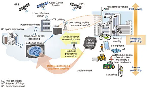
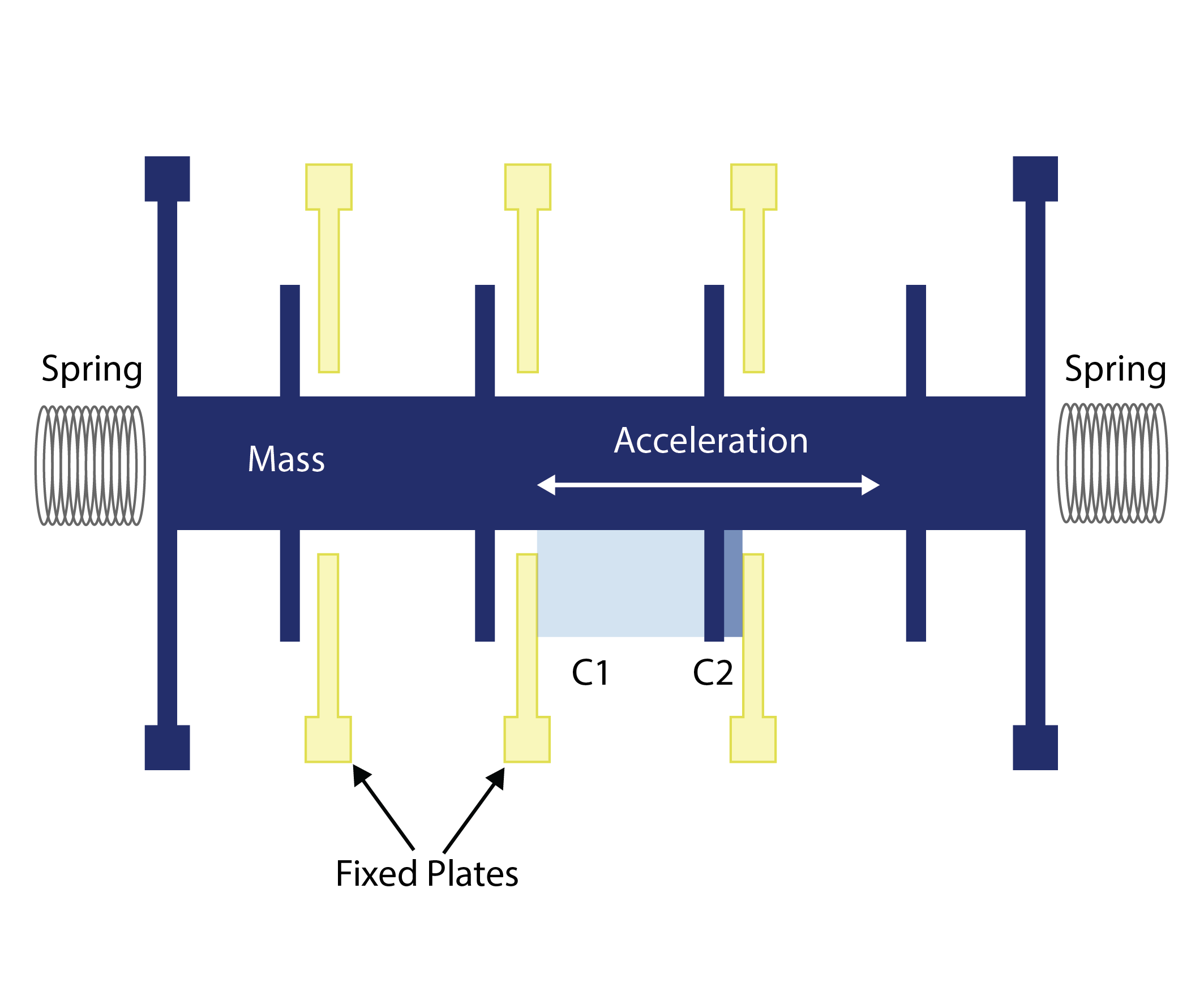
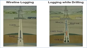


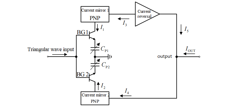
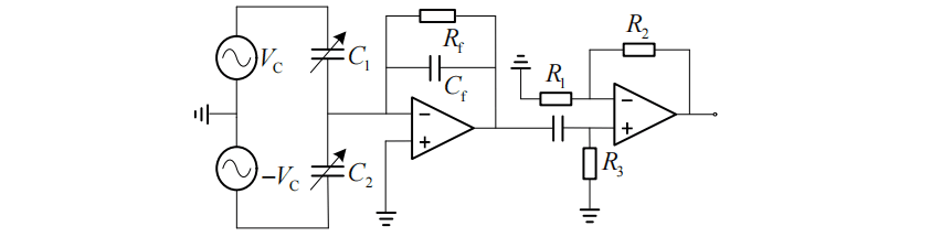
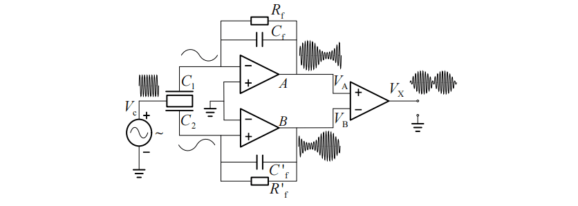
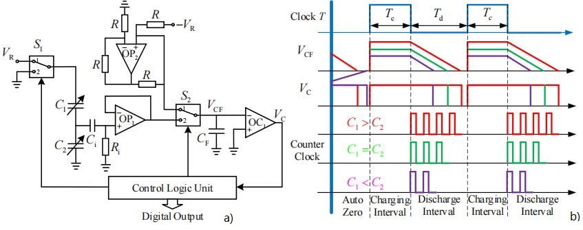
 Fig.1 Small GNSS Chip developed by Ericco WLCSP 1.70×2.84×0.5mm
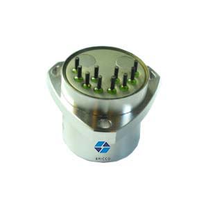
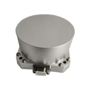
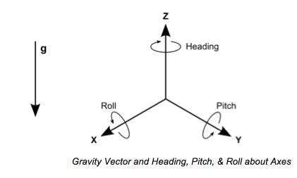
 Fig.3 Triaxial Accelerometer integrated in manufacturing environments